Gdt Tolerance Chart Pdf
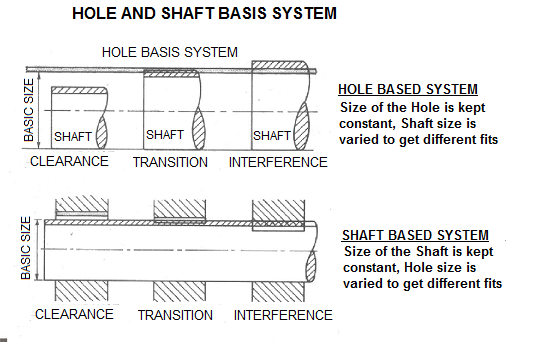
Hole And Shaft Basis Limits And Fits Hole Limits And Fits Hole And Shaft Tolerance

Can Gd T Extraction Really Be Automated 06 28 Quality Magazine
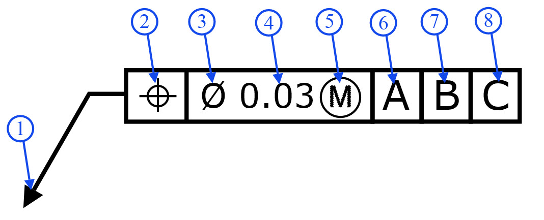
Feature Control Frame Gd T Basics
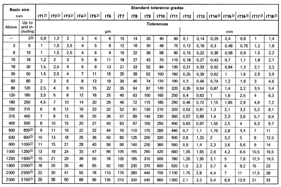
International Tolerance It Grades Table Chart Engineers Edge

Gd T In Tamil 15 Position True Position Location Geometric Characteristic Symbol Gd T Youtube

Gd T Tips Coaxiality Part Ii
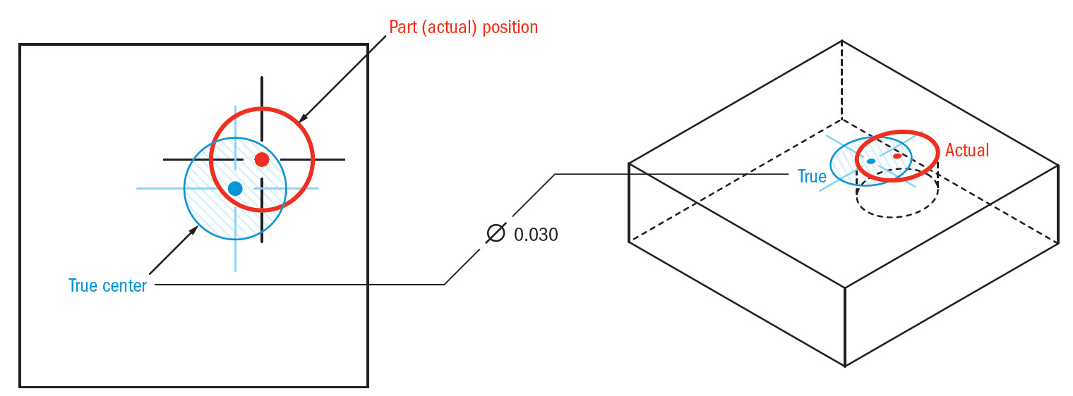
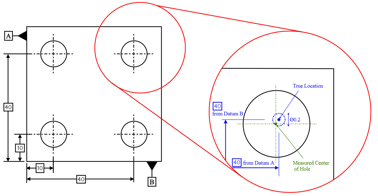
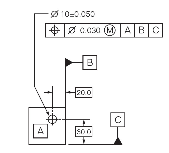
For example, without GD&T, the tolerance on a hole center is often X and Y plus or minus some amount That is a socalled “Square Tolerance” WIth GD&T, the tolerance is expressed as a round area This is a much more forgiving tolerance than a Square Tolerance if you think of drawing a circular whose edges just meet the corners of the.
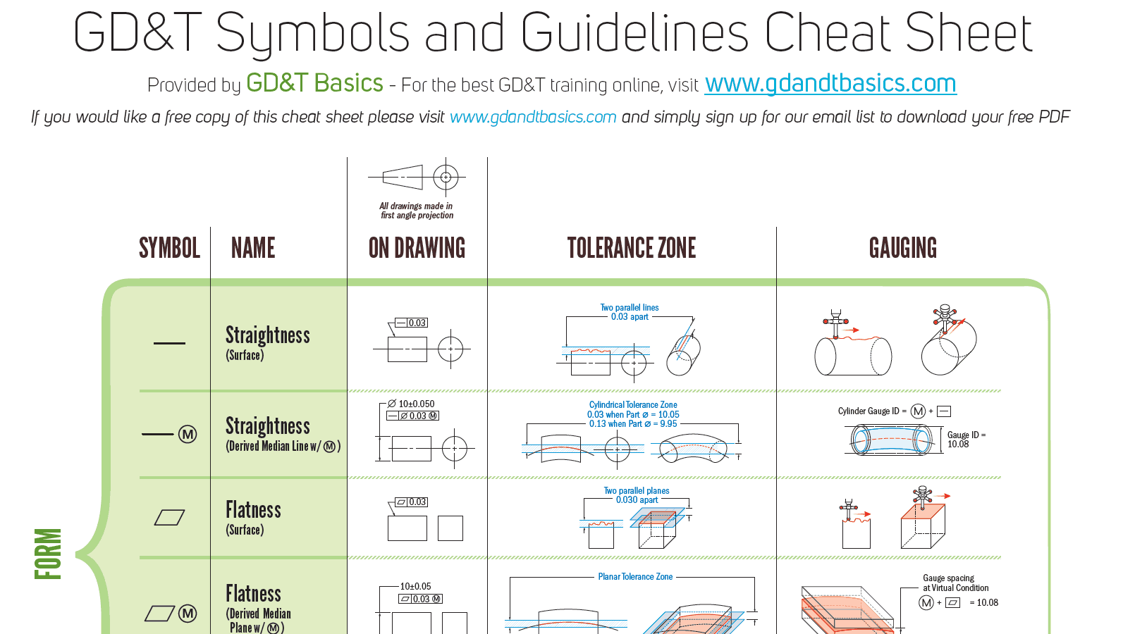
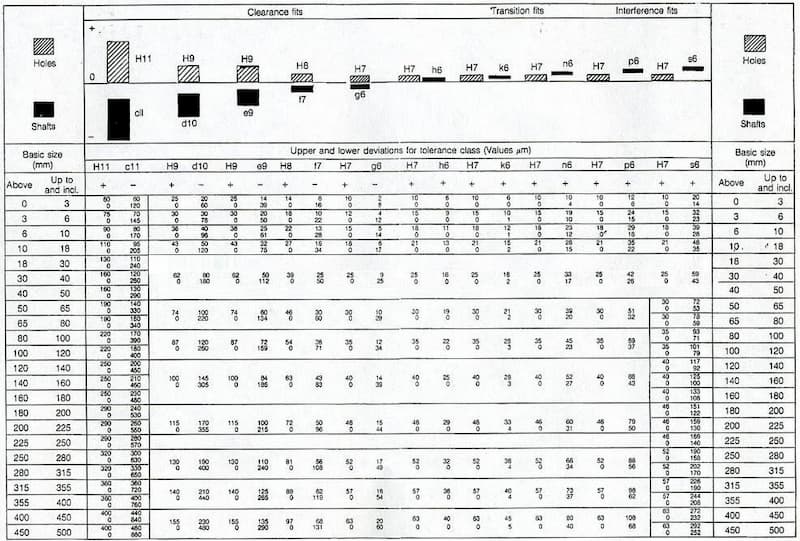
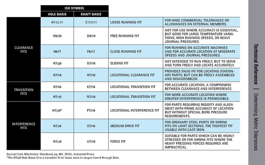
Gdt tolerance chart pdf. Geometric Dimensioning and Tolerancing (GD&T) is a system for defining and communicating engineering tolerancesIt uses a symbolic language on engineering drawings and computergenerated threedimensional solid models that explicitly describe nominal geometry and its allowable variation It tells the manufacturing staff and machines what degree of accuracy and precision is needed on each. 51 Dimensions, Tolerance and Related Attributes Dimension – ‘a numerical value expressed in appropriate units of measure and indicated on a drawing along with lines, symbols and notes to define the size/geometric characteristics of a part’ Variations in the part size comes from manufacturing processes. ) Note In each column, the upper figure is the upper dimensional tolerance, and the lower figure is the lower dimensional tolera Hole tolerance range class nce Hole dimensional tolerances for regularly used ˜tting Units µ m Standard dimension More than Not more than - - - - - - - - - - - - - - - ± 31 ± 26.
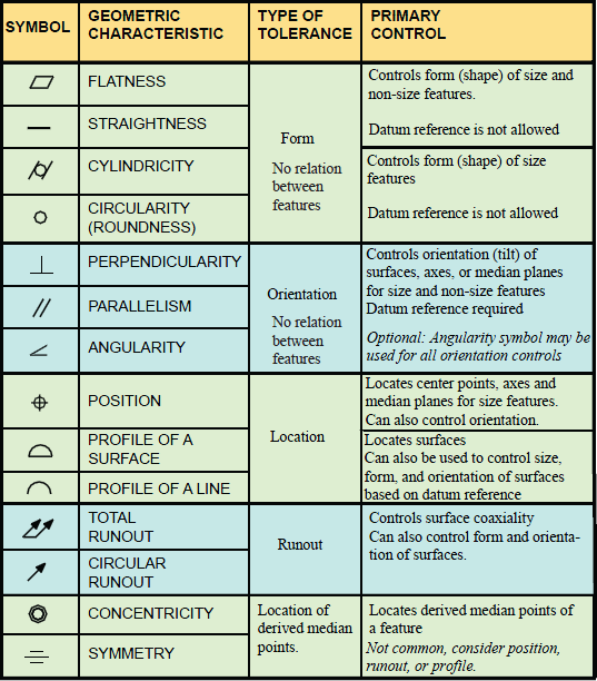
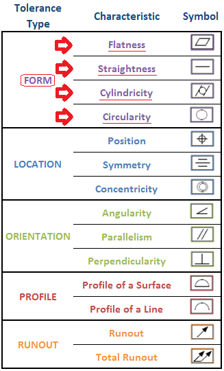
GD&T symbols chart and reference materials Geo Symbol Chart PDF · ASME and ISO Standands related to Product Defination and Metrology PDF The TecEase GD&T Glossary and free resource features explainations of Use this quick reference to find definitions of common GD&T symbols and terms geometry of a part separate from its size. Nov 17, 19 Explore AshleyMivec4G63's board "Geometric Tolerancing" on See more ideas about geometric tolerancing, geometric, technical drawing. GD&T affords however much or little tolerance the designer specifies Just as ubiquitous is the claim that using GD&T saves money, but these claims are never accompanied by cost or Return on Investment (ROI) analyses A much more fundamental reason for Figure 51 Drawing showing distance to.
) Note In each column, the upper figure is the upper dimensional tolerance, and the lower figure is the lower dimensional tolera Hole tolerance range class nce Hole dimensional tolerances for regularly used ˜tting Units µ m Standard dimension More than Not more than - - - - - - - - - - - - - - - ± 31 ± 26. The same part that fails with conventional tolerances may pass with GD&T tolerances The figure below illustrates this issue Notice that a square tolerance zone of /500" will allow a hole center location 707" away from the center if it is located in the squares' corner (diagonally) Remembering that a GD&T tolerance value is. 91 Position Tolerance 511 92 Concentricity & Symmetry Tolerances 513 10 Profi le Tolerance 514 11 Run Out Tolerances 518 12 Orientation Tolerances 519 13 Form Tolerances 521 131 Straightness 521 132 Flatness 523 133 Circulatity (Roundness) 523 134 Cylindricity 523 14 Conversion Charts 529.
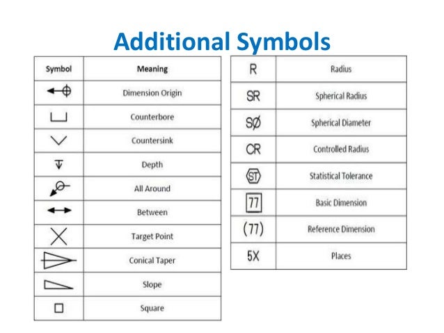
Æ Statistical Tolerance {77} Basic Dimension (77) Reference Dimension 5X Places Our GD&T Advisor software solution provides the automation you need to make manual GD&T methods a thing of the past!. The current standard for GD&T is ASME Y, from the American Society of Mechanical Engineers It replaces the 1994 version The rectangular box that contains a GD&T callout is known as the "feature control frame" A geometric tolerance shown in a feature control frame is always total, not plus/minus Depending on how it is used, it may be. Great for study and GD&T Certification preparation!.
This unique, stateoftheart solution accelerates the design process, saving valuable time, and. Dimensions Tolerances for basic dimensions on gage drawings are gagemakers’ tolerances Gagemakers’ tolerances are usually no more than 10% of the tolerance of the part All the tolerance for the gage comes from the tolerance for the part In other words, a gage may not accept a bad part, but it can reject a marginally good part. GD&T It consists of welldefined of symbols, rules, definitions and conventions, used on engineering drawings to accurately describe a part •GD&T is a precise mathematical language that can be used to describe the size, form, orientation, and location of part features •GD&T is also a design philosophy on how to design and dimension parts.
GD&T It consists of welldefined of symbols, rules, definitions and conventions, used on engineering drawings to accurately describe a part •GD&T is a precise mathematical language that can be used to describe the size, form, orientation, and location of part features •GD&T is also a design philosophy on how to design and dimension parts. Jan 26, 21 Find many great new & used options and get the best deals for Geometric Dimensioning and Tolerancing MAGNETIC GD&T Chart for CNC Shop at the best online prices at eBay!. 09 GD&T WALL CHART PDF Advanced Dimensional Press Bryan R Fischer Essential office and shop reference!.
Tolerance analysis is the process of taking known tolerances and analyzing the combination of these tolerances at an assembly level This chapter will define the process for analyzing tolerance stacks It will show how to set up a loop diagram to determine a nominal performance/assembly value and four tech. (GD&T) is a symbolic language used on engineering drawings and computer generated three‐dimensional solid models for explicitly describing nominal geometry and its allowable variation A datum is a feature of a part that acts as a master reference used to locate other features of the part A datum can be a point, a line, or a plane. GD&T symbols chart and reference materials Geo Symbol Chart PDF · ASME and ISO Standands related to Product Defination and Metrology PDF The TecEase GD&T Glossary and free resource features explainations of Use this quick reference to find definitions of common GD&T symbols and terms geometry of a part separate from its size.
Tolerance is the total amount a dimension may vary and is the difference between the upper (maximum) and lower (minimum) limits Tolerances are used to control the amount of variation inherent in all manufactured parts In particular, tolerances are assigned to mating parts in an assembly. Tolerance Zone of Pin Gauge Actual True 60° A A A A A A A A B B A A B B A A A A A A B B C C M 003 M 003 Flat datum block (Datum A) Flat datum block (Datum A) Part Gauge 003 M Planar Tolerance Zone M = 1008 Gauge spacing at Virtual Condition Actual Pin Position True position Tolerance Zone of Hole Gauge Datum A Fixed Rotated A 1 The. GD&T symbols chart and reference materials Geo Symbol Chart PDF · ASME and ISO Standands related to Product Defination and Metrology PDF The TecEase GD&T Glossary and free resource features explainations of Use this quick reference to find definitions of common GD&T symbols and terms geometry of a part separate from its size.
Æ Statistical Tolerance {77} Basic Dimension (77) Reference Dimension 5X Places Our GD&T Advisor software solution provides the automation you need to make manual GD&T methods a thing of the past!. Mechanical Tolerance Chart Data The following Engineering calculator will show the plus and minus tolerance for the specific ISO 286 Shaft tolerance data Enter your desired preferred tolerance grade and the nomial size Also see Table of Hole Tolerances per ISO 286 Preferred tolerance grade ISO 286;. Advantages of GD&T GD&T instructions are a significant improvement over the traditional methods GD&T is a compact language that can be understood by anyone who has learned the symbols and it replaces the numerous notes that were often used to describe the part.
Tolerance really like the flexibility this tolerancing technique offers them Manufacturers can easily reduce costs by accepting more parts 1000 5000 00 400 600 Figure 718A A large size tolerance and small location tolerance at MMC. ANSI And ISO Geometric Tolerancing Symbols There are several standards available worldwide to describe the symbols and the rules These are American Society of Mechanical Engineers, ASME Y145M09, (GD&T Geometric Dimensioning and Tolerancing) and International Organization for Standardization, ISO/TC 213, (GPS Geometrical Product Specification) and ISO/TC 10 Technical Product. A Tolerance Dimension is a dimension used if a feature’s size needs to be called out or to specify the location or something without applying GD&T principles to it They are typically given a plus/minus “±” tolerance but can have asymmetric limits as well.
51 Dimensions, Tolerance and Related Attributes Dimension – ‘a numerical value expressed in appropriate units of measure and indicated on a drawing along with lines, symbols and notes to define the size/geometric characteristics of a part’ Variations in the part size comes from manufacturing processes. Tolerance in relation to $$$$ • Cost generally increases with smaller tolerance – Small tolerances cause an exponential increase in cost – Therefore your duty as an engineer have to consider Do you need Φin or is 101in good enough?. Tolerance really like the flexibility this tolerancing technique offers them Manufacturers can easily reduce costs by accepting more parts 1000 5000 00 400 600 Figure 718A A large size tolerance and small location tolerance at MMC.
Jive Software Version 1500_jx, revision d0e3release_150jx. For example, without GD&T, the tolerance on a hole center is often X and Y plus or minus some amount That is a socalled “Square Tolerance” WIth GD&T, the tolerance is expressed as a round area This is a much more forgiving tolerance than a Square Tolerance if you think of drawing a circular whose edges just meet the corners of the. GD&T is a language based on a set of industry standards that will enable you to fully communicate your design and tolerance constraints to a manufacturer Along the way, we will review symbols and notations from Geometric Dimensioning and Tolerancing standards and describe how they relate to CAD geometry and manufacturing practices.
• ASME Y145 defines tolerance zones only and therefore reporting any measured value requires assumptions beyond the standard • ASME Y1451 GD&T math standard “This document is not intended as a gaging standard” Measurement Planning • Measurements can never “conform” to ASME Y145. Geometric Tolerancing Geometric Tolerancing Geometric tolerances state the maximum allowable variations of a form or its position from the perfect geometry implied on the drawing Traditional notes which explain geometric tolerance variations have been used in the past Presently, however, it is recommended that such tolerances be defined using the geometric characteristic symbols outlined in. GD&T affords however much or little tolerance the designer specifies Just as ubiquitous is the claim that using GD&T saves money, but these claims are never accompanied by cost or Return on Investment (ROI) analyses A much more fundamental reason for Figure 51 Drawing showing distance to.
(GD&T) is a symbolic language used on engineering drawings and computer generated three‐dimensional solid models for explicitly describing nominal geometry and its allowable variation A datum is a feature of a part that acts as a master reference used to locate other features of the part A datum can be a point, a line, or a plane. General Tolerance (from ASME Y145M09) Tolerances can be expressed 1 directly to a dimension 2 geometric tolerance 3 in a note 4 In a general tolerance block Limit dimensioningThe high limit is placed above the low limit 2 Plus and Minus TolerancingThe dim is given first and is. The geometric tolerance symbol adds geometric tolerances to parts and drawings using feature control frames The SOLIDWORKS software supports the ASME Y Geometric and True Position Tolerancing guidelines You can place geometric tolerancing symbols, with or without leaders, anywhere in a drawing, part, assembly, or sketch, and you can.
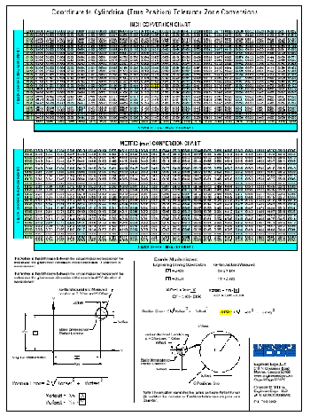
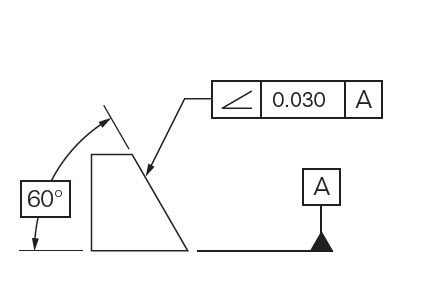
09 GD&T Wall Chart 30 1994 GD&T Wall Chart 30 Conversion Wall Chart 31 FoldOut Conversion Chart 31 Apparel 33 Golf Polos 34 Golf Hat 34 Tee Shirts 35 Coffee Mugs 3738 Onsite Training 39 Fundamentals of GD&T – 09 40 ASME Y Update Course 41 Applications of GD&T 42 GD&T for Plastics 43 Tolerance Stack. Tolerance Zone at 10±005 10±005 003 M Cylindrical Tolerance Zone 003 when Part ∅ = 1005 013 when Part ∅ = 995 Datum A 60° Datum A Datum A Datum A Two concentric cylinders 003 apart Two parallel planes 003 apart Uniform Linear Boundary About True Pro˜le 003 apart Datum B Datum A Datum A Tolerance Zone Uniform Surface Boundary. Geometric Tolerancing Geometric Tolerancing Geometric tolerances state the maximum allowable variations of a form or its position from the perfect geometry implied on the drawing Traditional notes which explain geometric tolerance variations have been used in the past Presently, however, it is recommended that such tolerances be defined using the geometric characteristic symbols outlined in.
Free shipping for many products!. • ASME Y145 defines tolerance zones only and therefore reporting any measured value requires assumptions beyond the standard • ASME Y1451 GD&T math standard “This document is not intended as a gaging standard” Measurement Planning • Measurements can never “conform” to ASME Y145. Dimensions Tolerances for basic dimensions on gage drawings are gagemakers’ tolerances Gagemakers’ tolerances are usually no more than 10% of the tolerance of the part All the tolerance for the gage comes from the tolerance for the part In other words, a gage may not accept a bad part, but it can reject a marginally good part.
This unique, stateoftheart solution accelerates the design process, saving valuable time, and. Shaft tolerance table (iso) ≥ < b10 c9 d8 e7 e8 f7 g7 h6 h7 h8 js7 k7 m7 n7 p7 r7 s7 t7 3 180 140 85 60 34 24 14 28 14 16 6 12 2 6 0 10 0 14 0 ±5 6 1 140 100 70 48 30 32 38 22 10 16 4 8 0 12 0 18 0 ±6 39 10. 09 GD&T Wall Chart 30 1994 GD&T Wall Chart 30 Conversion Wall Chart 31 FoldOut Conversion Chart 31 Apparel 33 Golf Polos 34 Golf Hat 34 Tee Shirts 35 Coffee Mugs 3738 Onsite Training 39 Fundamentals of GD&T – 09 40 ASME Y Update Course 41 Applications of GD&T 42 GD&T for Plastics 43 Tolerance Stack.

Asme Y14 5 18 Gd T Wallchart 18 Standard Products

Gd T Color Chart Pdf Engineering Tolerance Geometry

Engineering Tolerances Limits Fits And Gd T Explained Fractory

Geometric Tolerance Chart Engineering Tolerance Geometry
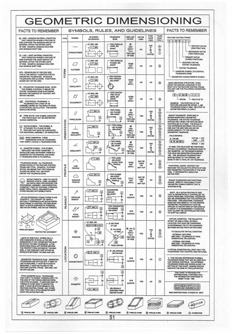
Geometric Dimensioning And Tolerancing Mindworks

Gd T By Cadd Pdf In 21 Cartesian Coordinates Systems Engineering Coordinates

Gd T Wall Chart 1 Pdf Theoretical Physics Differential Geometry

Gd T Symbols Gd T Basics
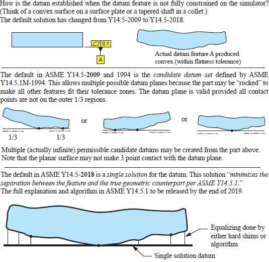
Gd T Systems Manufacturing Engineering Draft Drawing Basics

10 Useful Mechanical Engineering And Manufacturing Wall Charts Omnia Mfg Mechanical Engineering Mechanical Engineering Design Engineering
Gdt Tolerance Drone Fest

Gd T Systems Manufacturing Engineering Draft Drawing Basics

Gd T In Tamil 06 Feature Control Frame Tolerance Box Gd T Youtube

Gd T In Tamil Maximum Material Condition Mmc Gd T Youtube

True Position Chart Pdf Dat Night

1 D Tolerance Chart Automate

Drafting Door Symbol New Image Result For Mechanical Engineering Drawing Symbols Chart Pdf Mechanical Engineering Engineering Electrical Symbols

Tolerance Stackup Tolerance Analysis And Tolerancing Manual Plus And Minus Edition Sigmetrix

Gd T In Tamil 13 Parallelism Orientation Geometric Characteristic Symbol Gd T Youtube

Geometric Dimensioning And Tolerancing Magnetic Gd T Chart For Cnc Shop Usefulmagnets Geometric Tolerancing Geometric Mechanical Engineering Design

Pdf Exploiting The Process Capability Of Profile Tolerance According Gd T Asme Y14 5m Semantic Scholar

Geometric Dimensioning Symbols Chart The Future

Gd T Symbols Reference Guide From Sigmetrix Engineering Symbols Mechanical Engineering Design Mechanical Design

Gd T Presentation Pdf Document

Learn Gd T Completely In Tamil Geometric Dimensioning And Tolerancing Youtube

Effective Training Inc Solutions Gd T Training
Gd T Material Modifiers What Are They How Do They Work Imaginit Manufacturing Solutions Blog

Feature Control Frame Tolerance Box Gd T English Youtube

New Asme Y14 5 09 Standards For Gd T Machine Design
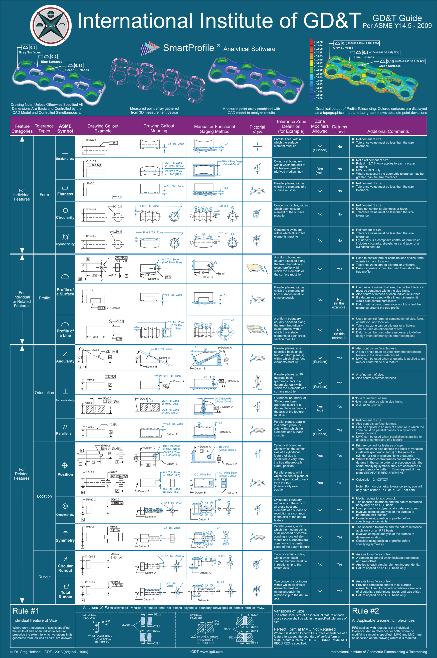
Gd T Reference Chart Asme Y14 5 09 Gd T Symbols
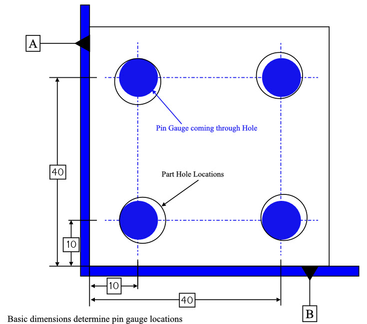
True Position Gd T Basics

Gd And T Basics Drone Fest
Gd T Symbols Charts For Engineering Drawing Drafting Geotol

Gd T In Tamil 07 Introduction Of Geometric Characteristic Symbols Gd T Symbols Gd T Youtube
Circularity Gd T Basics

Wallet Sized Gd T Symbol Reference Card Omnia Mfg Engineering Symbols Geometric Tolerancing Reference Cards
True Position Gd T Basics
Limits Fits Types Of Fits Explained Tolerance Charts Fractory
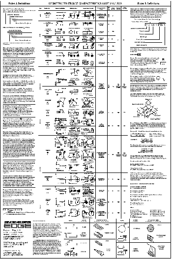
Ultimate Gd T Wall Chart Laminated Asme Y14 5 09 Engineering Books And Supplies Store

Gd T 101 An Introduction To Geometric Dimensioning And Tolerancing
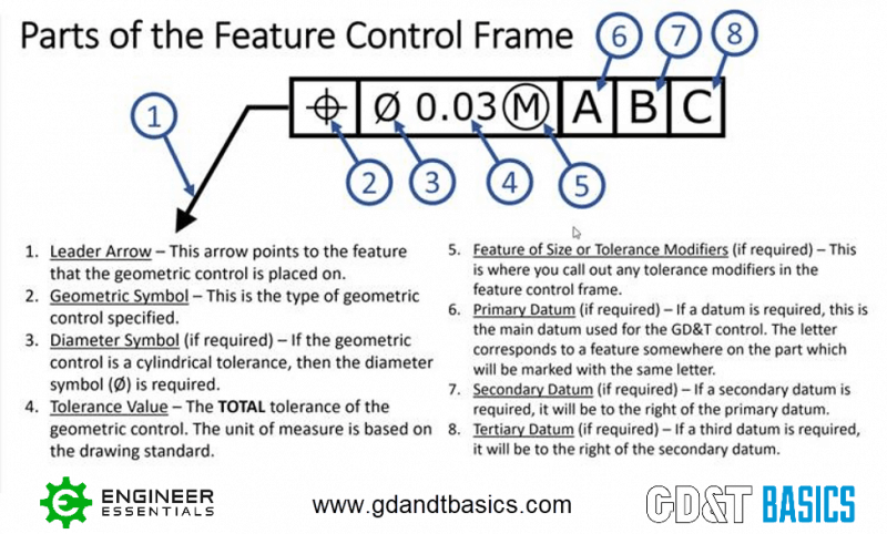
The Asme Y14 5 Gd T Standard Gd T Basics
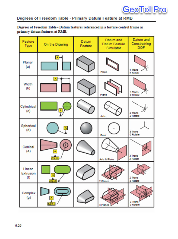
Gd T Symbols Charts For Engineering Drawing Drafting Geotol
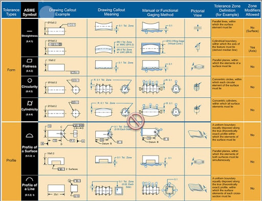
Cad Cam Cae Links Free Tutorial Software Download Mechanical Jobs Gd T Poster Gd T Symbols Explanation With Example Drawing Callouts Meaning

Pdf Selection Of Machining Datum And Allocation Of Tolerance Through Tolerance Charting Technique

True Position Gd T Basics
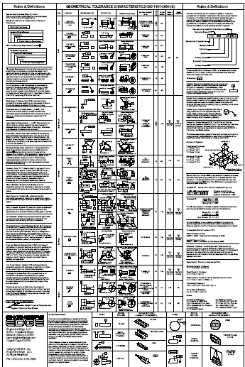
Ultimate G T Wall Chart Laminated Iso 1101 04 E Engineering Books And Supplies Store

Gd T Basics Wall Chart Cartesian Coordinates Systems Engineering Coordinates
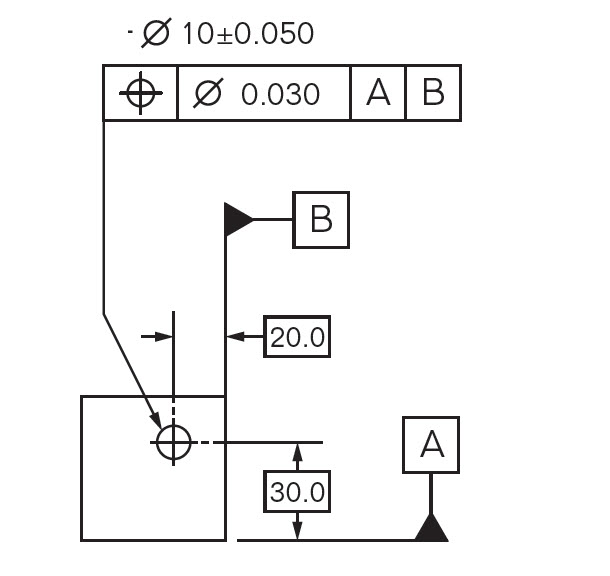
True Position Gd T Basics

Gd T In Tamil 08 Flatness Form Geometric Characteristic Symbol Gd T Youtube
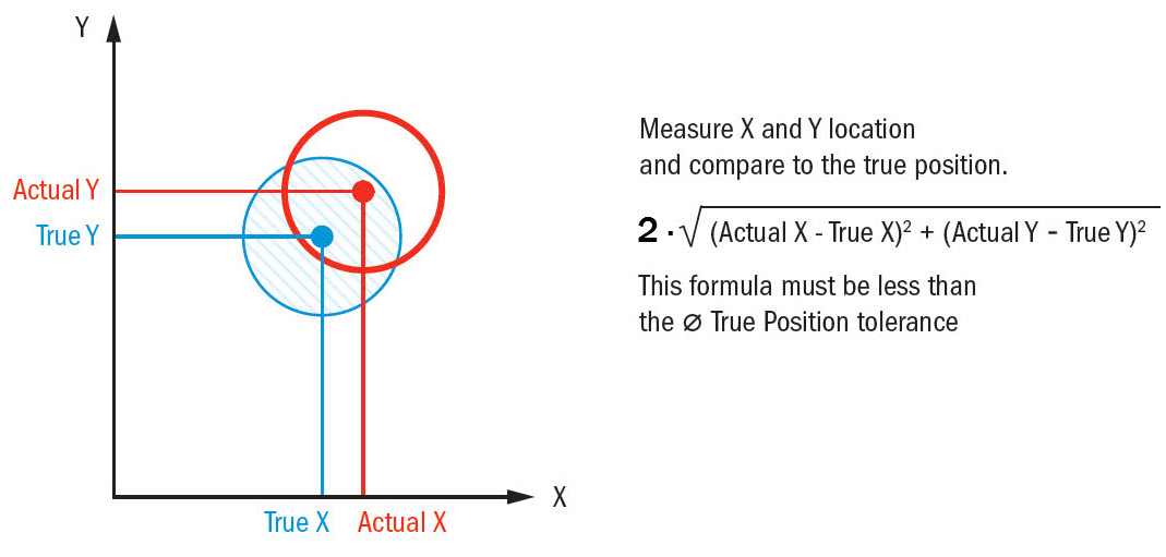
True Position Gd T Basics

Pdf Gd T Naughtyn N Academia Edu

Gd T For Beginners Mmc Bonus Tolerance Explained In 3d

Application Of Gd T An Overview By Sigmetrix
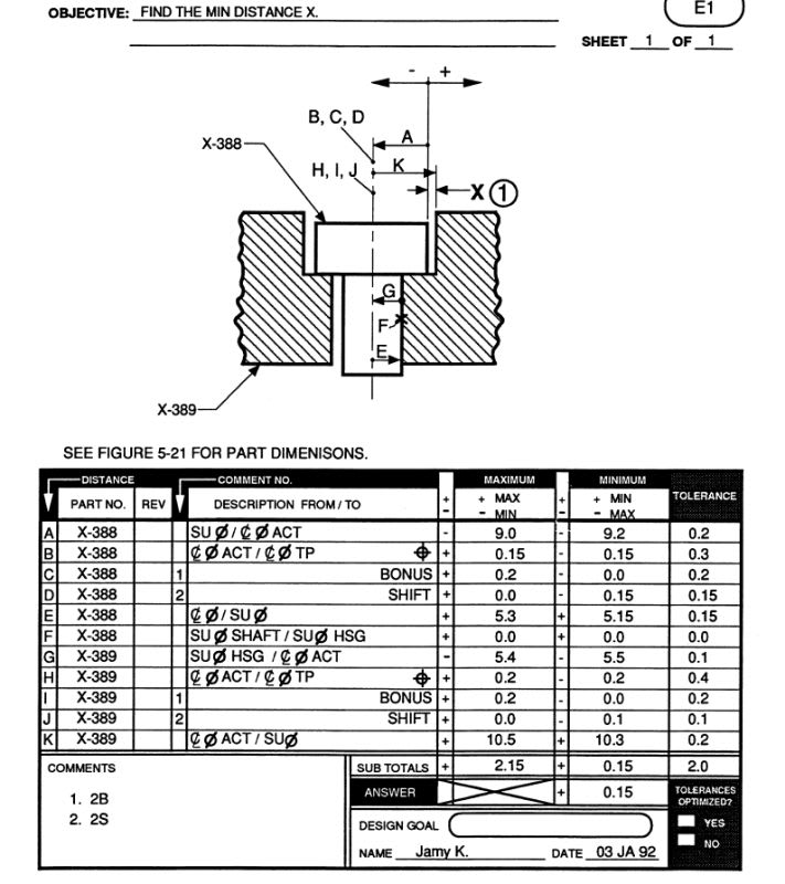
Alex Krulikowski Workbook Max Dimension 2 15 Shown On The Minimum X Distance Drafting Standards Gd T Tolerance Analysis Eng Tips

True Position Chart Pdf Dat Night
True Position Gd T Basics

Gd T Symbols Reference Guide From Sigmetrix Mechanical Engineering Design Mechanical Symbols Mechanical Design

Pdf Exploiting The Process Capability Of Position Geometric Tolerance According Gd T Asme Y14 5m

Gd T Basics Wall Chart Engineering Tolerance Plane Geometry
Gd T True Position Coordinate Conversion Wall Chart Laminated Engineering Books And Supplies Store

Terminologies Of Limits Fits And Tolerances Youtube
Angularity Gd T Basics

Gd T In Tamil 18 Profile Of A Surface Profile Geometric Characteristic Symbol Gd T Youtube

Pdf Exploiting The Process Capability Of Profile Tolerance According Gd T Asme Y14 5m Semantic Scholar
Engineering Drawings Gd T For The Quality Engineer

Gt D Symbols Engineering Technology Engineering
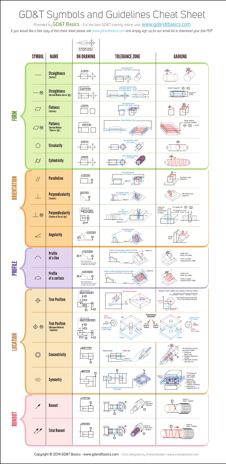
Why Engineers Should Care To Learn Gd T Engineerdog
Geometric Dimensioning And Tolerancing Wikipedia
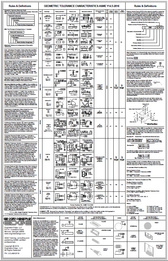
Asme Y14 5 18 Ultimate Gd T Wall Chart Laminated Engineering Books And Supplies Store
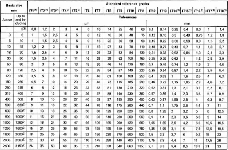
Limits Fits Types Of Fits Explained Tolerance Charts Fractory
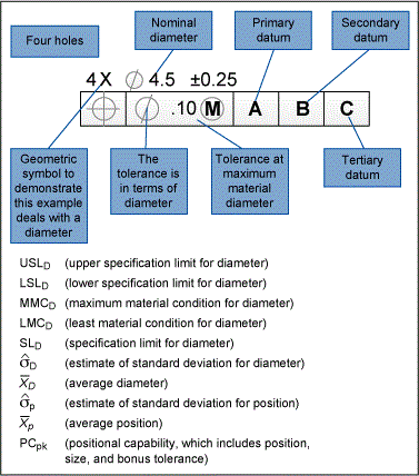
Process Capability Surface Finish Example Part 2
Gd T Ppt
Limits Fits And Tolerances Understanding Definitions Selection Practical Use
True Position Gd T Basics

Geometric Dimensioning And Tolerancing Wikipedia

Gd T Symbols With Examples Riansclub

Free Gd T Pdf Wall Chart Gd T Basics


